Layflat Hose Leaking at Coupling: 7 Causes and How to Fix Each One
Introduction
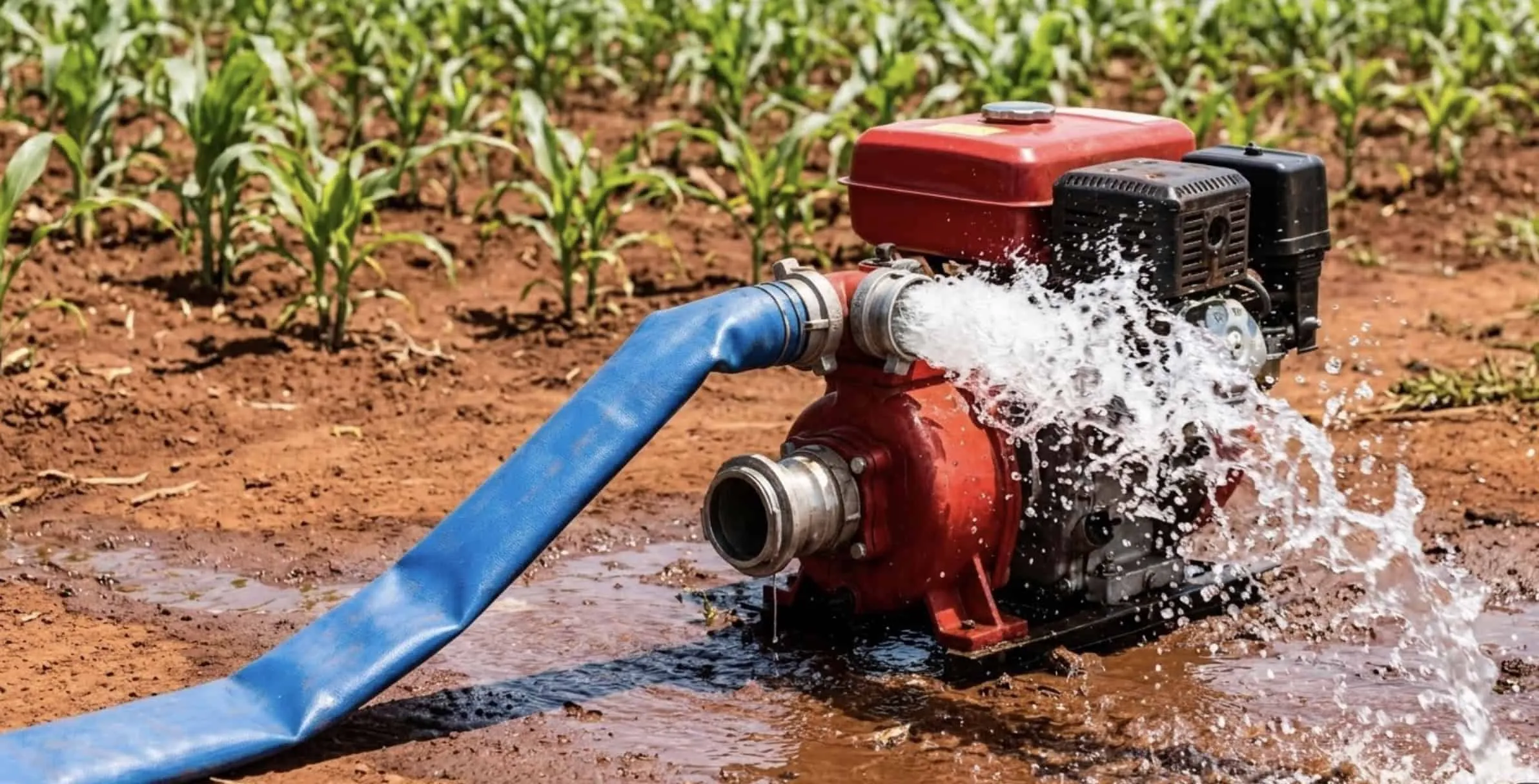
A layflat discharge hose leaking at the coupling is one of the most common — and most disruptive — problems in agricultural irrigation, construction dewatering, and industrial water transfer. The leak wastes water, drops system pressure, and if left unaddressed, causes the coupling to fail completely under load.
Most coupling leaks have an identifiable cause, but the system must be shut down and fully depressurized before inspection. Use the hose, coupling, clamp, pump, and site-safety instructions that apply to the actual assembly. Do not touch, tighten, disconnect, or test a coupling while it is pressurized.
This guide walks through every root cause of layflat hose coupling leaks, with step-by-step repair instructions for each — covering camlock (cam and groove) fittings, Bauer couplings, and BSP threaded connections.
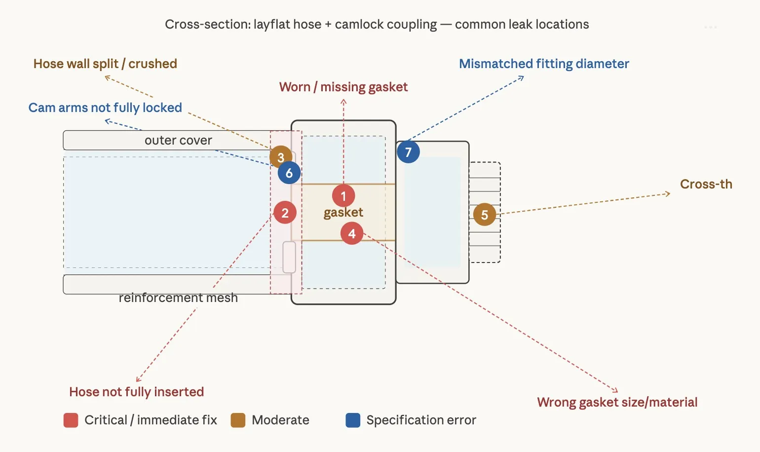 layflat hose coupling leak causes diagram
Cause 1: Worn, Cracked, or Missing Gasket
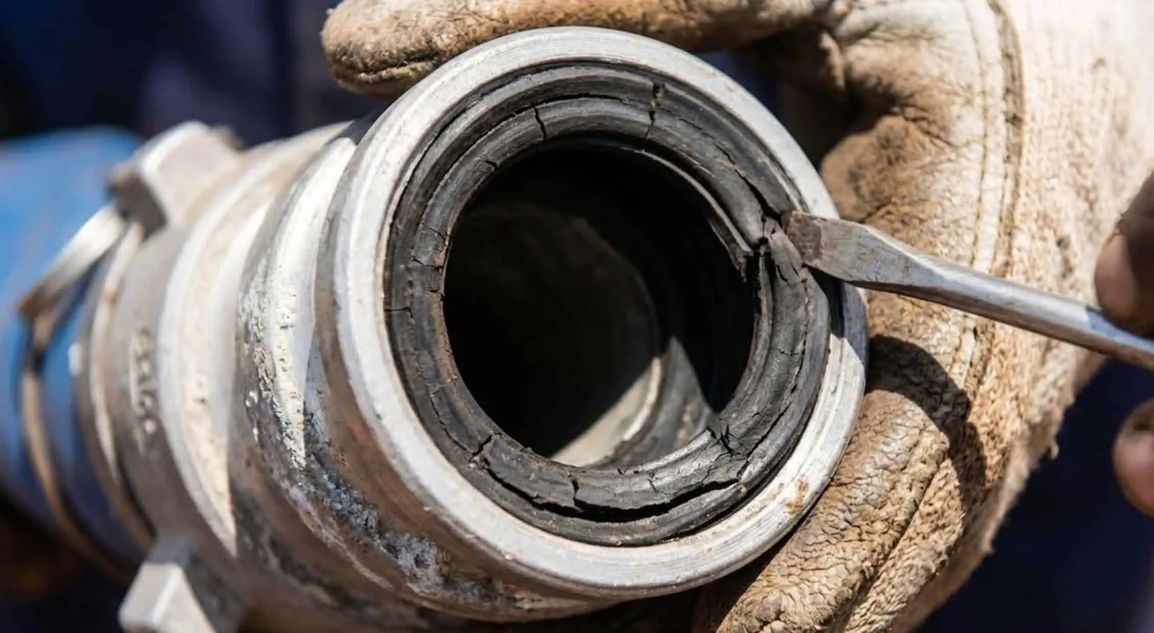
The gasket is a rubber ring seated in the face of the female camlock coupler. It creates the primary pressure seal between the two coupling halves. Over time — particularly in hot climates where equipment is left in direct sun — the gasket hardens, flattens, and loses its elasticity. Once it can no longer conform to the opposing face, water escapes around the perimeter under pressure.
 camlock gasket
How to identify: Disconnect the coupling. Look inside the female socket. The gasket should be a full, even-thickness rubber ring sitting flush in the groove. If it is cracked, compressed flat, deformed, or absent entirely, this is your cause.
How to fix:
Depressurize the system and disconnect the coupling
Remove the old gasket using a flathead screwdriver — do not use a sharp blade near the seating groove
Clean the groove with a dry cloth — remove any debris or mineral deposits
Press the new gasket firmly into the groove, ensuring it seats evenly all the way around with no raised sections
Reconnect the coupling and pressurize gradually — check for seepage
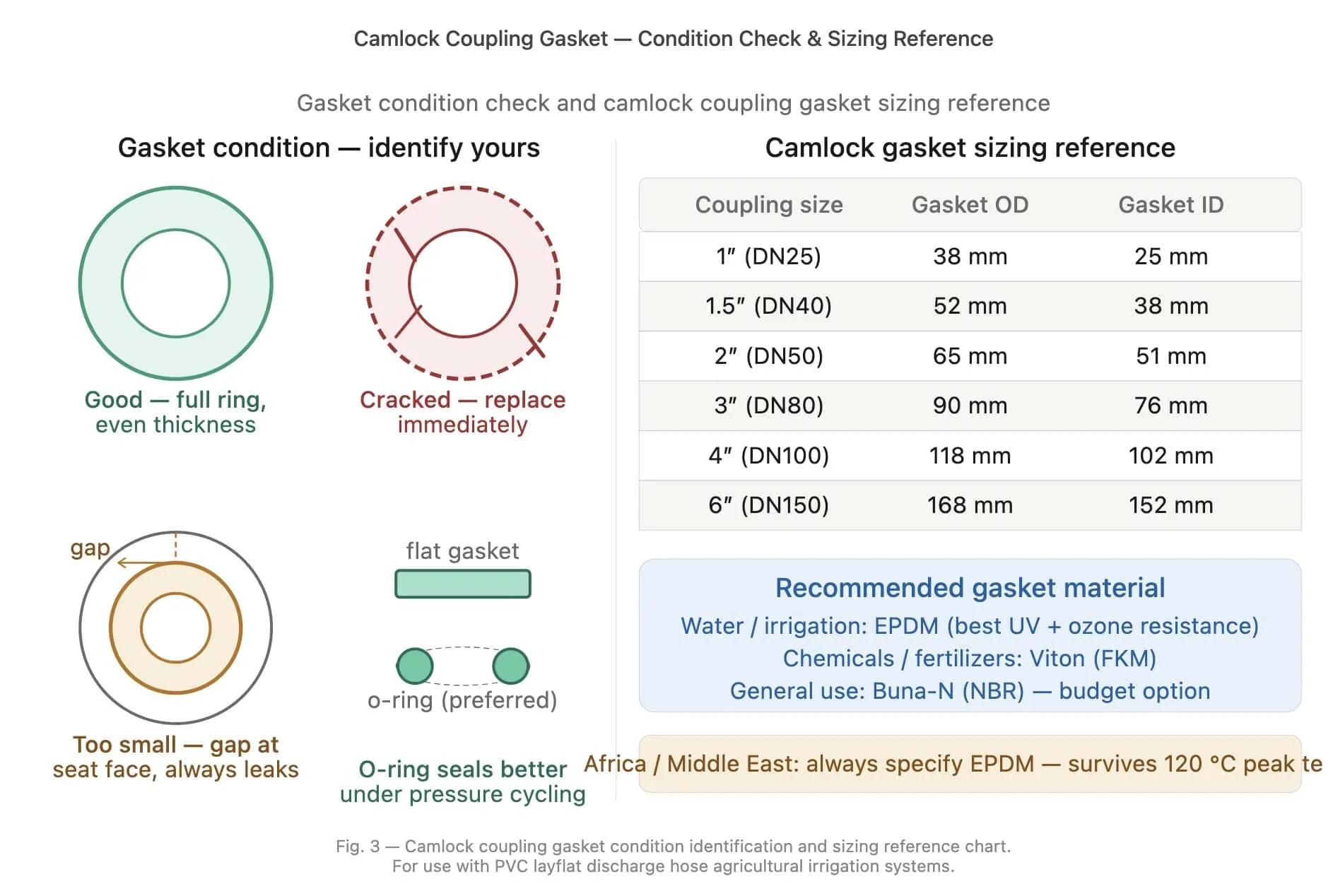
Gasket selection: Match the exact coupler model and size, then check the coupling manufacturer's compatibility table for the conveyed liquid, concentration, and operating-temperature range. EPDM, NBR, and FKM have different compatibility limits; no single material is the correct choice for every water, fertilizer, fuel, or chemical service.
Prevention: Inspect the gasket and sealing surfaces at the interval required by the coupling manufacturer and the site's risk-based maintenance plan. Replace a gasket when it is cracked, cut, swollen, hardened, flattened, chemically degraded, or no longer seats correctly.
 camlock gasket sizing reference chart
Cause 2: Hose End Not Fully Inserted into the Coupling Barrel
Camlock couplings for layflat hose use a barbed or smooth barrel that the hose slides over or into, secured by hose clamps or a crimp ferrule. If the hose is not pushed to full insertion depth before the clamp is tightened, there is a gap between the hose wall and the coupling body — water escapes through this gap under pressure, appearing as a leak "at the coupling" but actually originating at the insertion point.
How to identify: With the system isolated and depressurized, compare the insertion depth and clamp position with the coupling or hose-assembly manufacturer's instructions. Movement, a visible gap, or a clamp outside the specified engagement zone requires the assembly to be corrected before reuse.
How to fix:
Depressurize and disconnect
Loosen the hose clamp
Use only an assembly lubricant approved for the hose, coupling, and conveyed liquid, if the manufacturer's procedure calls for one
Push the hose firmly to full insertion depth — the hose end should be visible at the inner edge of the coupling barrel's stop shoulder
Reposition the clamp to the center of the engagement zone, not at the very end
Tighten the specified clamp or ferrule using its manufacturer's installation method and torque or dimensional criteria. A universal torque value does not apply across clamp designs, sizes, and hose constructions.
Pressurize and check
Cause 3: Hose Wall Split or Crushed at the Insertion Point
If the hose wall at the coupling end has been mechanically damaged — split longitudinally from over-tightening, or crushed flat from improper storage — the deformed section cannot form a seal against the coupling barrel regardless of how tightly the clamp is applied. Water finds the path of least resistance through the wall irregularity.
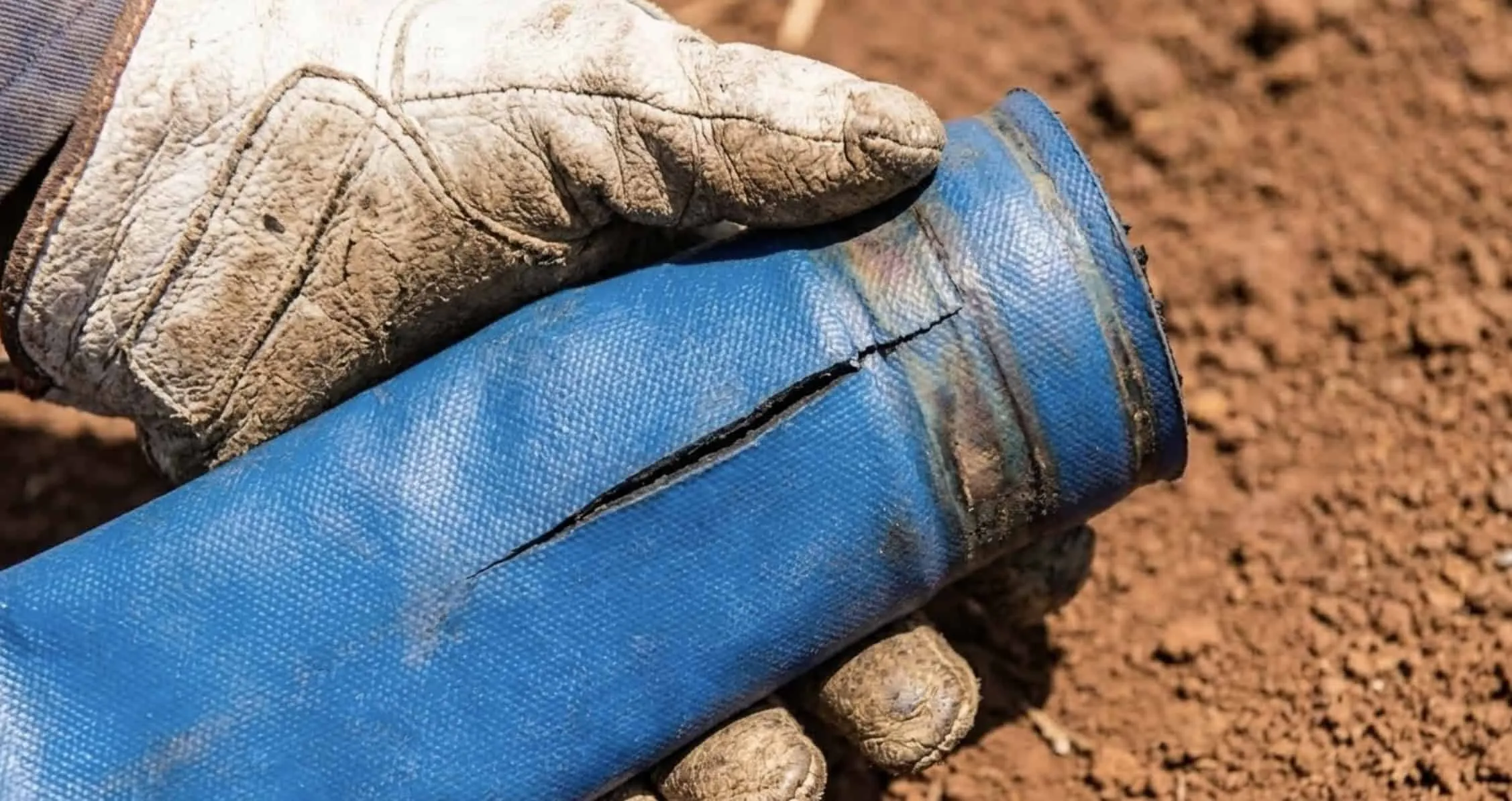 Hose Wall Split or Crushed at the Insertion Point
How to identify: Disconnect the depressurized assembly and examine the hose end and adjacent section carefully. Look for longitudinal splits, exposed reinforcement, flattened areas that do not recover, hardening, or discoloration at the clamp contact zone.
How to fix:
There is only one correct fix: cut off the damaged end and re-insert a fresh hose section.
Depressurize and disconnect
Following the hose and coupling manufacturer's assembly procedure, make a clean perpendicular cut beyond all visible and suspected damage
Examine the cut face — the wall should be uniform, the reinforcement mesh intact, and the bore circular
Re-insert onto the coupling barrel and re-clamp per Cause 2 procedure
How much hose to cut: Do not reuse any section with damaged reinforcement, permanent deformation, heat damage, or chemical degradation. If the acceptable remaining length, end preparation, or field-attachable coupling procedure cannot be confirmed, replace the hose assembly.
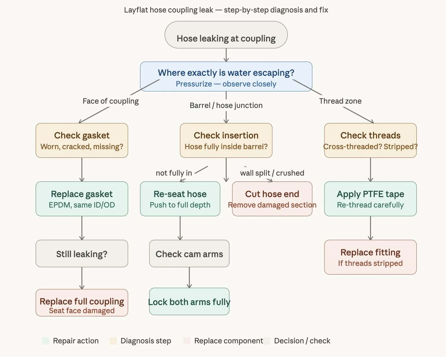 layflat hose coupling leak repair flowchart
Cause 4: Wrong Gasket Size or Material for the Application
A gasket that is the correct material but wrong diameter will not seal, regardless of how tightly the coupling is assembled. This is particularly common when gaskets are sourced locally from hardware suppliers who stock standard plumbing gaskets that do not match camlock face dimensions.
How to identify: Remove and identify the gasket only after isolation and depressurization. Compare its part number or measured dimensions with the coupling manufacturer's data; visual similarity to a general plumbing gasket is not sufficient.
How to fix: Replace it with the gasket specified for the female coupler model, nominal size, conveyed material, and temperature range. Record the coupling manufacturer, part number, material, and service conditions when ordering replacements.
Cause 5: Cross-Threaded or Stripped BSP Connection
For layflat hose systems where the coupling attaches to a pump outlet via BSP (British Standard Pipe) thread rather than a camlock face seal, cross-threading is a frequent cause of leaks. Cross-threading occurs when the male thread is started at an angle, causing the threads to engage incorrectly — they appear tight but leave a spiral leak path.
How to identify: A properly threaded connection feels smooth as it engages. A cross-threaded connection requires excessive force to turn and may feel gritty. After assembly, if the fitting is visibly cocked at an angle rather than perpendicular to the pump face, it is cross-threaded.
How to fix:
For cross-threading (threads intact): Unscrew completely, clean both threads, and restart engagement by hand — turn the male fitting counterclockwise until you feel it drop into the thread start, then turn clockwise. Never use a wrench until at least three full turns have been completed by hand.
For damaged or stripped threads: Remove the fitting from service and replace the damaged component. Thread tape or sealant cannot restore damaged load-bearing threads.
Use only the thread sealant and application method specified for the actual BSP or NPT connection, conveyed liquid, temperature, and fitting material. Cam-and-groove faces seal at the gasket and do not use thread tape on the sealing face.
Cause 6: Cam Arms Not Fully Locked
On camlock (cam and groove) couplings, the two spring-loaded cam arms must be pressed down to the fully locked position after insertion. A partial lock — where the arms are down but not snapped through center — allows the female coupler to separate from the male adapter under pressure, with leakage preceding full disconnection.
How to identify: Shut down, isolate, and fully depressurize the system before approaching the coupling. Inspect both arms, pins, lobes, locking features, adapter groove, gasket seat, and coupling body for incomplete engagement, wear, corrosion, cracks, or deformation. Never test arm movement by hand on a pressurized assembly.
How to fix: Depressurize before re-seating the arms. Attempting to push cam arms to the locked position under pressure risks sudden disconnection. Once depressurized, push both arms simultaneously and firmly downward until they click past center. Pressurize and recheck.
Prevention: Always use both hands when connecting camlock couplings — one to hold the female coupler body, one to press both arms. Never assume one arm locking is sufficient; both must engage simultaneously for proper sealing.
Cause 7: Mismatched Fitting Diameter
A 2-inch hose connected to a 2.5-inch male adapter, or a 3-inch hose onto a 2-inch fitting — these combinations are attempted more often than expected in field conditions when the correct size is unavailable. The mismatch creates a fundamental geometric incompatibility that no gasket or clamp can overcome.
How to identify: After isolation and disconnection, verify the nominal hose and coupling sizes from their markings, part numbers, or dimensional drawings. Do not accept a connection based on appearance alone.
How to fix: Use the coupling and attachment system specified for the hose size and construction. There is no reliable field workaround for mismatched diameters.
Prevention Checklist: Stopping the Leak Before It Starts
Many layflat hose coupling leaks can be prevented through documented inspection, compatible components, correct assembly, and controlled pressure testing.
Before each season:
Remove all gaskets and inspect — replace any that show cracking, flattening, or permanent deformation
Check cam arms for spring tension — arms that do not snap firmly should be replaced
Inspect each hose end and the adjacent loaded section for wall damage, exposed reinforcement, splitting, or hardening
Verify coupling size matches hose size on all connections
Use gasket lubricant only when the coupling manufacturer approves the product for the gasket material and conveyed liquid
During assembly:
Clean coupling faces and hose end before connecting
Push hose to full insertion depth before clamping
Engage cam arms with both hands simultaneously
Tighten hose clamps evenly — do not over-torque
Pressurize gradually on first use — do not open pump to full flow immediately
Storage:
Disconnect all couplings before storing hose between seasons
Store gaskets in a sealed bag away from direct sunlight and ozone sources (electric motors)
Never store couplings with hose clamps fully tightened — the sustained pressure accelerates hose wall deformation at the insertion zone
Frequently Asked Questions
Why does mylayflat hose leak at the coupling only when the pump is at full pressure?
Pressure-dependent leakage can result from an incorrect or damaged gasket, worn coupling surfaces, incomplete arm engagement, a damaged hose attachment, pressure surge, or an assembly rating below the system demand. Shut down and depressurize the system, then inspect the complete assembly. Do not assume that a harder gasket alone will correct the cause.
Can I use PTFE tape on camlock couplings?
No. Camlock couplings seal on the gasket face, not on threads. PTFE tape has no sealing function on a camlock face-seal connection. It should only be used on BSP or NPT threaded connections.
How do I stop a layflat hose coupling from leaking in the field with no spare parts?
Shut down and depressurize the system. Do not return a leaking coupling to service with tape, extra clamps, or another improvised seal. Isolate the line until the correct compatible gasket, coupling, attachment hardware, or hose assembly is installed and inspected.
My layflat hose leaks at the coupling only after it has been running for 10–15 minutes. Why?
Time-dependent leakage can have several causes, including changing fluid temperature, pressure surges, gasket incompatibility, coupling wear, or movement at the hose attachment. Record the operating pressure, liquid and ambient temperatures, and time to leakage; then shut down and inspect the complete assembly against the component ratings.
How often should I replace camlock gaskets on agricultural hose systems?
There is no universal calendar or operating-hour interval. Follow the coupling manufacturer's instructions and set the inspection and replacement interval from service severity, conveyed liquid, temperature, UV and ozone exposure, pressure cycles, previous findings, and the consequence of failure. Replace the gasket whenever inspection shows damage, degradation, or loss of correct seating.
Technical References
- Dixon Procedure 3003: Inspecting Cam & Groove Couplings
- Dixon Coupling Procedures: inspection, installation, and hydrostatic testing
These references describe one manufacturer's products and procedures. Apply the instructions and ratings for the actual hose, coupling, clamp, gasket, pump, and conveyed liquid in your system.